Raspberry pi zero 2Wを入手したので備忘録として書きます。
焦電型赤外線センサ
以下の焦電型赤外線センサをamazonで購入しました。

このセンサは、人物や物体が温度に応じて放射している赤外線を検出して出力します。
動作確認
 |
| www.amazon.co.jp |
VIN端子にRaspberry Pi Zeroの 3.3V(1番pin)、
GNG端子にRaspberry Pi ZeroのGND(9番pin)に接続して、
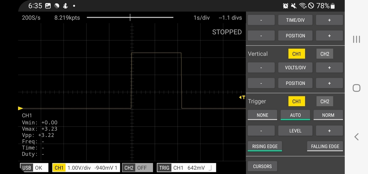
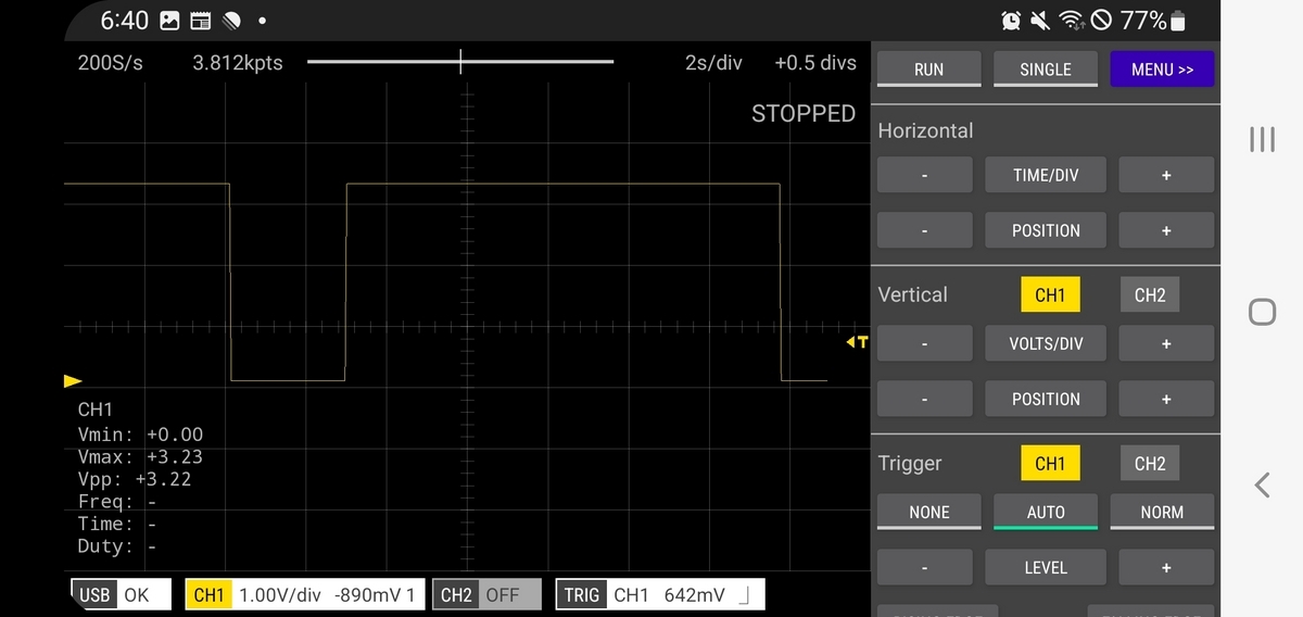
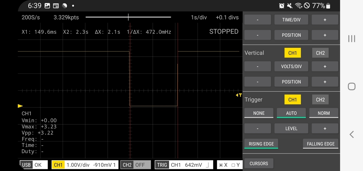
OUT端子の波形を確認してみました。
3.3Vを供給して、信号レベルは約3.2Vでした。
人を検出したとき(人が動いたとき)
OUT信号はH(3.2V)になり、約2秒後にL(0V)になりました。
動き続けた場合
OUT信号はH(3.2V)の状態を続け、動作をやめるとL(0V)になりました。
動作をやめてから(Lになってから)、直ぐ動作した場合
約2秒Lを継続した後にH(3.2V)になりました。
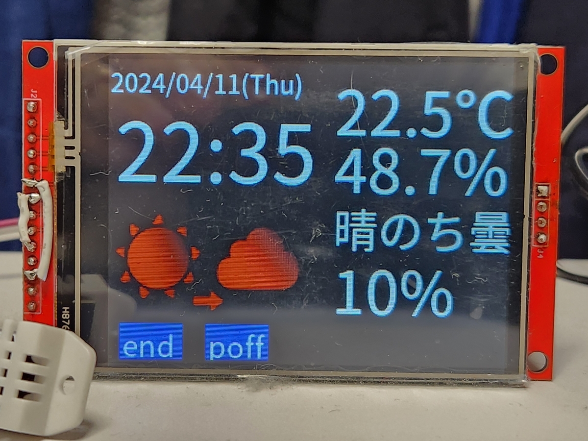
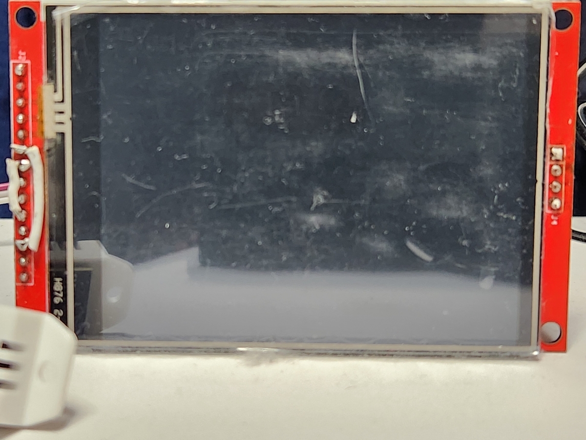
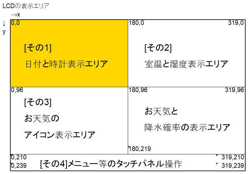
LCDのLED点灯制御
人が動いたときにLEDを点灯し、一定時間経過したらLEDを消灯するようにしたいと思います。
Raspberry Pi Zeroとの接続
|
焦電センサ |
Raspberry Pi Zero |
|
|
VIN |
3.3V |
1 |
|
OUT |
GPIO27 |
13 |
|
GND |
GND |
9 |
プログラム
GPIOの設定
GPIO27を人検知用の信号(PIR_PIN)として設定します。
変数 PIR_countは一定期間(今回は5分間)の人検知回数を保存します。
(後でどの程度の頻度で人検知しているかモニタするのに使用したいと考えています。)
#---------------------------------------------------------
#人感センサ

import RPi.GPIO as GPIO
import threading

PIR_PIN =27
GPIO.setmode(GPIO.BCM)
GPIO.setup(PIR_PIN,GPIO.IN)
PIR_count = 0
callback関数
先ほど設定したGPIOのPIR_PIN信号が立ち上がった時に割り込み処理として、このcallback関数を呼び出します。
この関数は、人検知の回数PIR_countを1プラスして、LEDを点灯させます。
そして、30秒後にPIR_check関数を呼び出す新しいタイマを起動します。
(古いタイマは、念のためキャンセルしてから新しいタイマをスタートしてます。)
#人感センサ入力を割り込み設定する
# 割り込みルーチンでLED点灯して30sタイマを起動する。
def callback(pin):
    global PIR_count,old_PIR_timer
    PIR_count = PIR_count + 1
    LCD_led(23,1)

    new_PIR_timer = threading.Timer(30.0, PIR_check)
    old_PIR_timer.cancel()
    new_PIR_timer.start()
    old_PIR_timer = new_PIR_timer

#GPIO.add_event_detect(PIR_PIN,GPIO.RISING,callback=callback)PIR_PN信号の割り込み処理を有効にするには、上記のコメントアウトした箇所です。
メインプログラムで有効にしているのでここではコメントアウトしています。
PIR_check関数
人を検知したときの割り込み処理(callback関数)で30秒後に呼ばれます。
この関数は、LEDを消灯して、callback関数で起動したタイマを停止します。
#---------------------------------------------------------------------
# 30s後人がいない場合LEDを消灯してタイマも停止する。
def PIR_check():
    global PIR,PIR_count,old_PIR_timer
    print("人検知",PIR_count,"LED消灯")
    LCD_led(23,0)
    old_PIR_timer.cancel()

#old_PIR_timer = threading.Timer(60.0, PIR_check)
#old_PIR_timer.start()
PIR_count_time関数
一定期間(今回は5分間)、人検知の回数をカウントするプログラムです。
300秒(5分)間隔で自分自身を呼び出して、「今の時間、温度、湿度、人検知回数」を出力します。
def PIR_count_time():
    import datetime
    global PIR_count,humi,temp
    PIR_count_timer = threading.Timer(300.0, PIR_count_time)
    PIR_count_timer.start()
    now = datetime.datetime.now()
    time_now = now.time().strftime("%H:%M:%S")
    #humi, temp = sensor.read()
    print(time_now,f'{temp:.01f}',"℃",f'{humi:.01f}',"%","PIR=",PIR_count)
    PIR_count = 0
#--------------------------------------------------------------------
メインプログラム
赤字の部分が今回追加したプログラムになります。
if __name__ == '__main__':
# libフォルダのライブラリを参照できるようにする。
import sys
sys.path.append('./lib')
from LCD_led import LCD_led
from LCD_disp import LCD_set,setup_disp,time_disp,now_daytime
from LCD_disp import temp_disp,weather_disp,weather_text_disp,weather_icon_disp
from LCD_disp import touch_disp,poff_disp
from weather_get import weather_get
from check_wifi import check_wifi
import time
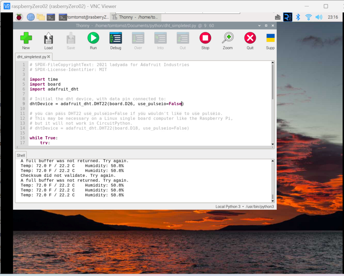
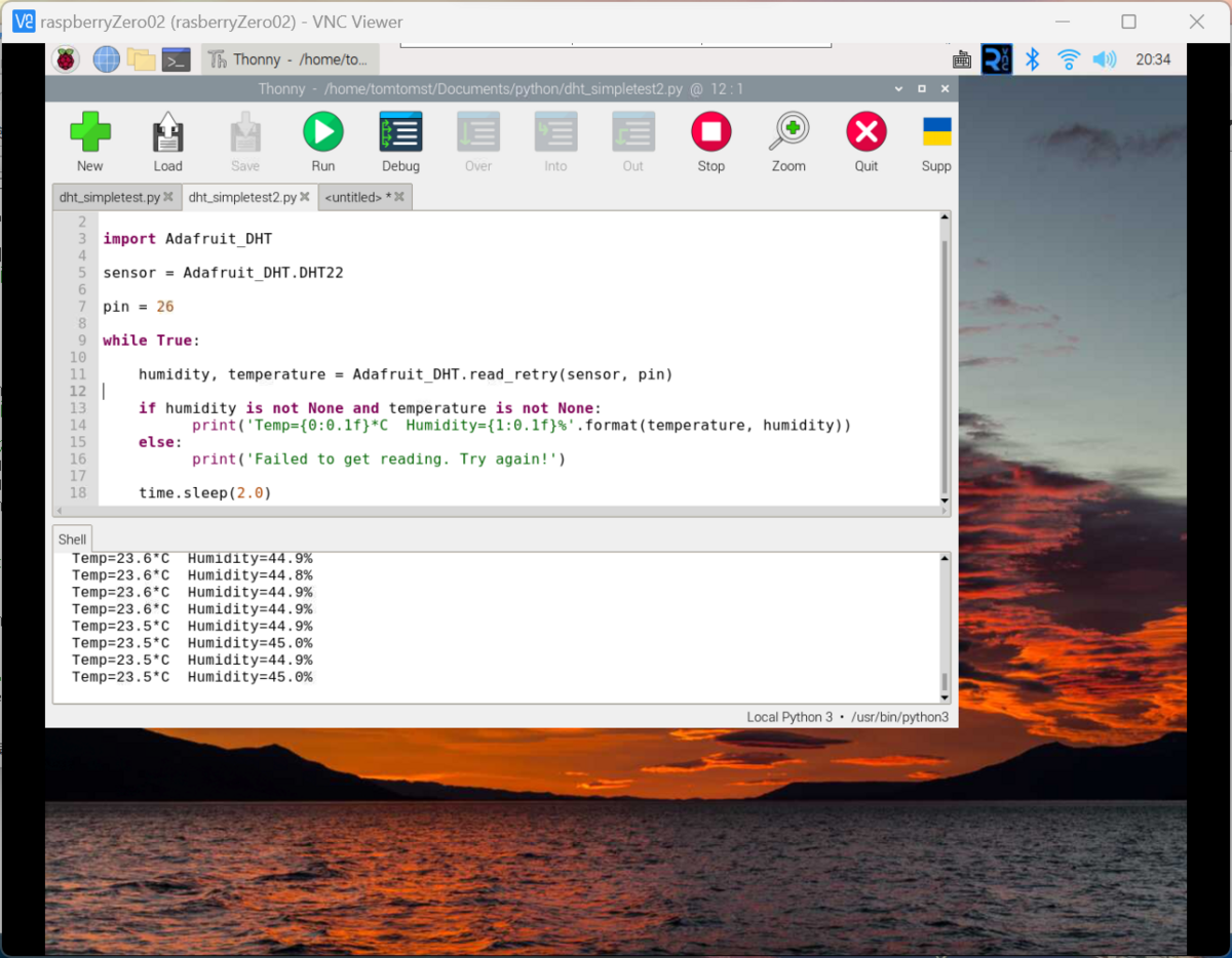
#---DHT22温度センサの初期設定-----
import Adafruit_DHT
sensor = Adafruit_DHT.DHT22
pin = 26
#------------------
setup_main()
touch_disp("")
#人検知の割り込みを有効にする
GPIO.add_event_detect(PIR_PIN,GPIO.RISING,callback=callback)
#60秒後にPIR_check関数を起動するタイマを設定する
old_PIR_timer = threading.Timer(60.0, PIR_check)
#タイマをスタートする
old_PIR_timer.start()
#5分(300秒)間隔で人検知回数を出力する
PIR_count = 0
PIR_count_time()
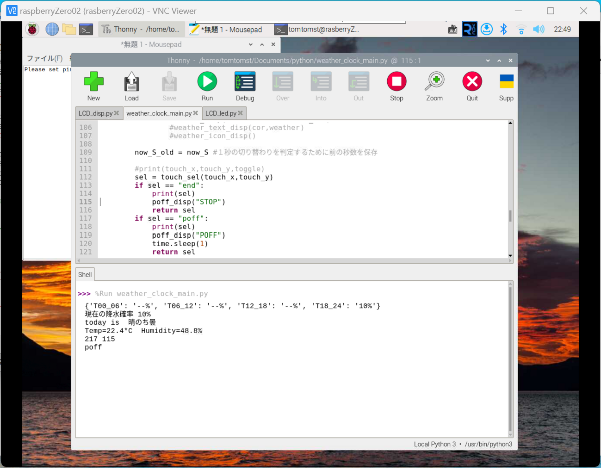
sel = main_01()
# import osでシャットダウンできるようにする
import os
# import RPi.GPIO as GPIO
time.sleep(1)
if sel =="end":
# GPIO.cleanup()
sys.exit()
if sel == "poff":
os.system('sudo shutdown -h now')
その他修正したプログラム
PIR_count_time関数で、最新の温度と湿度を5分間隔で出力するようにしたので、
setup_main関数とmain_01関数内で使用している変数tempとhumiをグローバル変数にしています。
#--------------------------------------------------------------
def setup_main():
global temp,humi
LCD_set() #LCDの初期設定
LCD_led(23,1) #LCDのLED点灯
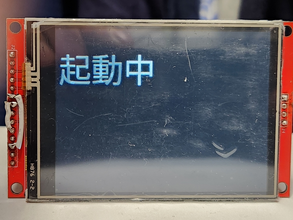
setup_disp() #起動中表示
time.sleep(1) #1秒wait
#今の日時を取得
today_n,time_n,now_M_S,now_S = now_daytime()
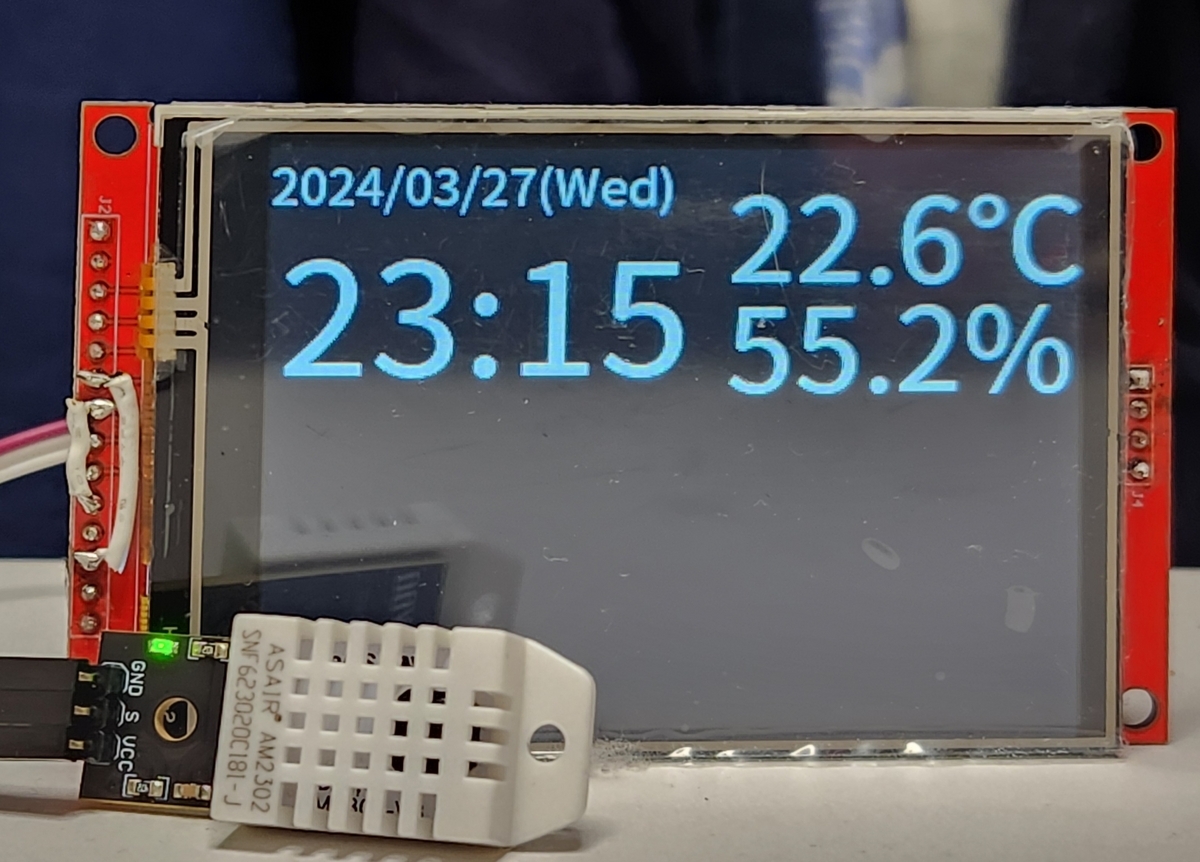
#時計表示
time_disp(today_n,time_n)
#温度取得
humi, temp = Adafruit_DHT.read_retry(sensor, pin)
if humi is not None and temp is not None:
#温度表示
temp_disp(temp,humi)
else:
print('Failed to get reading. Try again!')
while True:
if check_wifi():
print('Wi-Fi is available.')
break
else:
print('Wi-Fi is not available.')
time.sleep(1)
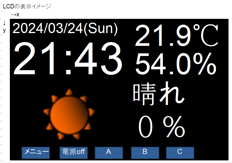
#お天気を取得
cor,weather,weather_url = weather_get()
#お天気をLCDへ表示
weather_disp(cor,weather,weather_url)
#weather_text_disp(cor,weather)
#weather_icon_disp()
#-------------------------------------------------
def main_01():
global touch_x,touch_y,temp,humi
now_S_old = "--"
(touch_x,touch_y) = (0,0)
while True:
#今の日時を取得
today_n,time_n,now_M_S,now_S = now_daytime()
if now_S != now_S_old: #1秒に1回処理するためにこの処理を追加
#0秒になったら時計表示
if now_S == "00" :
time_disp(today_n,time_n)
print(today_n,time_n)
if now_S[1] == "0": #10秒毎に処理
#温度取得
humi, temp = Adafruit_DHT.read_retry(sensor, pin)
if humi is not None and temp is not None:
#print('Temp={0:0.1f}*C Humidity={1:0.1f}%'.format(temp, humi))
#温度表示
temp_disp(temp,humi)
#weather_icon_disp()
else:
print('Failed to get reading. Try again!')
#天気予報表示
if now_M_S == "00:00":
print(time_n)
i = 0
while (i < 10):
if check_wifi():
print('Wi-Fi is available.')
#お天気を取得
cor,weather,weather_url = weather_get()
#お天気をLCDへ表示
weather_disp(cor,weather,weather_url)
break
else:
print('Wi-Fi is not available.')
time.sleep(1)
now_S_old = now_S #1秒の切り替わりを判定するために前の秒数を保存
#print(touch_x,touch_y,toggle)
sel = touch_sel(touch_x,touch_y)
if sel == "end" or sel == "poff":
print(sel)
time.sleep(1)
poff_disp(sel)
return sel
(touch_x,touch_y) = (0,0)
以上